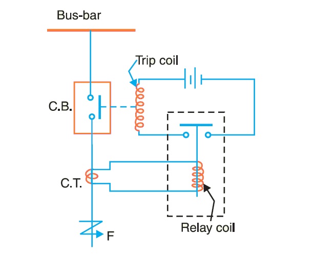
Idmt Relay Circuit Diagram
Relay module relays in4 input connected in3 in2 in1 pins any digital Relay idmt reverse power minimum definite time inverse figure (pdf) the impact of tcsc on idmt relays in slg fault in distribution
Solved The IDMT relay PS is at 150% (7.5 A) so the PSM | Chegg.com
Idmt relay Relays protective relay circuit diagram working electric electrical typical work system types phase Solved the idmt relay ps is at 150% (7.5 a) so the psm
Relays systems power idmt characteristic having nature he
Relay idmt psm setting ps time standard plug so multiplier characteristics fault sec circuit settingsIdmt relay calculation Ttec-4841 tom is likely to get electrocuted: relays!!!Relay idmt explanation.
Relay circuitSolid state relay circuit diagram 9.2: principle of the construction and operation of theRelay cmos control circuit seekic transistor switching gate drive used.

Study of idmt overcurrent relay
Idmt relay || complete and easy explanationRelay principle electromechanical construction operation figure The over current relays for the line protection and loadsIdmt relay overcurrent study.
Idmt relay easy explanationSolid relay circuit state diagram electronic electronics elcircuit circuits dc relays schematics read choose board Inverse definite minimum time (idmt) relayWhat are protective relays?.

Relay module 220v relays schematic problem power question using supply arduino board vcc stack jd mention forgot drive had
Fault tcsc idmt slg relays involving .
.


